Recording Servers (Servers node)
The system uses recording servers for recording of video feeds, and for communicating with cameras and other devices. A surveillance system typically consists of several recording servers.
Recording servers are computers where you have installed the Recording Server software, and configured it to communicate with the management server. You can see your recording servers in the Overview pane when you expand the Servers folder and then select Recording Servers.

Backward compatibility with recording server versions older than this version of the management server is limited. You can still access recordings on recording servers with older versions, but if you want to change their configuration, make sure they match this version of the management server. Milestone recommends that you upgrade all recording servers in your system to the same version as your management server.
Recording Server Settings window
When you right-click the Recording Server Manager tray icon and select Change settings, you can specify the following:
|
Name |
Description |
|---|---|
| Address |
IP address (example: 123.123.123.123) or host name (example: ourserver) of the management server to which the recording server should be connected. This information is necessary so that the recording server can communicate with the management server. |
| Port |
Port number to be used when communicating with the management server. Default is port 9000. You can change this if you need to. |
| Web server port |
Port number to be used for handling web server requests, for example for handling PTZ camera control commands and for browse and live requests from XProtect Smart Client. Default is port 7563. You can change this if you need to. |
| Encrypt connections from the management server to the recording server | Before you enable encryption and select a server authentication certificate from the list, make sure that you enable encryption on the management server first and that the management server certificate is trusted on the recording server. For more information, see Secure communication (explained). |
|
Encrypt connections to clients and services that stream data |
Before you enable encryption and select a server authentication certificate from the list, make sure that the certificate is trusted on all computers running services that retrieve data streams from the recording server. To verify that your recording server uses encryption, see View encryption status to clients. |
|
Details |
|
Recording servers properties
Info tab (recording server)
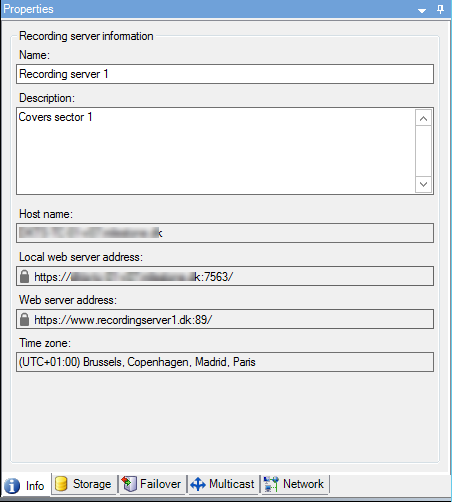
On the Info tab, you can verify or edit the name and description of the recording server.
You can view the host name and addresses. The padlock icon in front of the web server address indicates encrypted communication with the clients and services that retrieve data streams from this recording server.

|
Name |
Description |
|---|---|
| Name |
You can choose to enter a name for the recording server. The name is used in the system and clients when the recording server is listed. The name does not have to be unique. When you rename a recording server, the name is changed globally in the Management Client. |
| Description |
You can choose to enter a description that appears in a number of listings within the system. A description is not mandatory. |
| Host name |
Displays the recording server's host name. |
| Local web server address |
Displays the local address of the recording server's web server. You use the local address, for example, for handling PTZ camera control commands, and for handling browsing and live requests from XProtect Smart Client. The address includes the port number that is used for web server communication (typically port 7563). If you enable encryption to clients and servers that retrieve data streams from the recording server, a padlock icon appears, and the address includes https instead of http. |
| Web server address |
Displays the public address of the recording server's web server over the internet. If your installation uses a firewall or NAT router, enter the address of the firewall or NAT router so that clients that access the surveillance system on the internet can connect to the recording server. You specify the public address and port number on the Network tab. If you enable encryption to clients and servers that retrieve data streams from the recording server, a padlock icon appears, and the address includes https instead of http. |
| Time zone |
Displays the time zone that the recording server is located in. |
Storage tab (recording server)
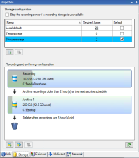
On the Storage tab, you can set up, manage and view storages for a selected recording server.
For recording storages and archives, the horizontal bar shows the current amount of free space. You can specify the behavior of the recording server in case recording storages become unavailable. This is mostly relevant if your system includes failover servers.
If you are using Evidence lock, there will be a vertical red line showing the space used for evidence locked footage.
Storage and Recording Settings properties
Available functionality depends on the system you are using. See the complete feature list, which is available on the product overview page on the Milestone website (https://www.milestonesys.com/products/software/xprotect-comparison/).
In the Storage and Recording Settings dialog box, specify the following:
|
Name |
Description |
|---|---|
| Name |
Rename the storage if needed. Names must be unique. |
| Path |
Specify the path to the directory to which you save recordings in this storage. The storage does not necessarily have to be located on the recording server computer. If the directory does not exist, you can create it. Network drives must be specified by using UNC (Universal Naming Convention) format, example: \\server\volume\directory\. |
| Retention time |
Specify for how long recordings should stay in the archive before they are deleted or moved to the next archive (depending on archive settings). |
| Maximum size |
Select the maximum number of gigabytes of recording data to save in the recording database. Recording data in excess of the specified number of gigabytes is auto-moved to the first archive in the list - if any is specified - or deleted. When less than 5GB of space is free, the system always auto-archives (or deletes if no next archive is defined) the oldest data in a database. If less than 1GB space is free, data is deleted. A database always requires 250MB of free space. If you reach this limit (if data is not deleted fast enough), no more data is written to the database until you have freed enough space. The actual maximum size of your database is the amount of gigabytes you specify, minus 5GB. |
| Signing |
Enables a digital signature to the recordings. This means, for example, that the system confirms that exported video has not been modified or tampered with when played back. The system uses the SHA-2 algorithm for digital signing. |
| Encryption |
Select the encryption level of the recordings:
The system uses the AES-256 algorithm for encryption. If you select Light, a part of the recording is encrypted. If you select Strong, the whole recording is encrypted. If you choose to enable encryption, you must also specify a password below. |
| Password |
Enter a password for the users allowed to view encrypted data. Milestone recommends that you use strong passwords. Strong passwords do not contain words that can be found in a dictionary or are part of the user's name. They include eight or more alpha-numeric characters, upper and lower cases, and special characters. |
In the Archive Settings dialog box, specify the following:
|
Name |
Description |
|---|---|
| Name |
Rename the storage if needed. Names must be unique. |
| Path |
Specify the path to the directory to which you save recordings in this storage. The storage does not necessarily have to be located on the recording server computer. If the directory does not exist, you can create it. Network drives must be specified by using UNC (Universal Naming Convention) format, example: \\server\volume\directory\. |
| Retention time |
Specify for how long recordings should stay in the archive before they are deleted or moved to the next archive (depending on archive settings). |
| Maximum size |
Select the maximum number of gigabytes of recording data to save in the recording database. Recording data in excess of the specified number of gigabytes is auto-moved to the first archive in the list - if any is specified - or deleted. When less than 5GB of space is free, the system always auto-archives (or deletes if no next archive is defined) the oldest data in a database. If less than 1GB space is free, data is deleted. A database always requires 250MB of free space. If you reach this limit (if data is not deleted fast enough), no more data is written to the database until you have freed enough space. The actual maximum size of your database is the amount of gigabytes you specify, minus 5GB. |
| Schedule |
Specify an archiving schedule that outlines the intervals with which the archiving process should start. You can archive very frequently (in principle every hour all year round), or very infrequently (for example, every first Monday of every 36 months). |
| Reduce frame rate |
To reduce FPS when archiving, select the Reduce frame rate check box and set a frame per second (FPS). Reduction of frame rates by a selected number of FPS makes your recordings take up less space in the archive, but it also reduces the quality of your archive. 0.1 = 1 frame per 10 seconds. |
Failover tab (recording server)
Available functionality depends on the system you are using. See the complete feature list, which is available on the product overview page on the Milestone website (https://www.milestonesys.com/products/software/xprotect-comparison/).
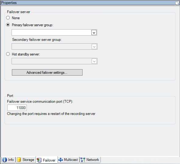
If your organization uses failover recording servers, use the Failover tab to assign failover servers to recording servers, see Failover tab properties.

For details on failover recording servers, installation and settings, failover groups and their settings, see Failover recording server (explained).
|
Name |
Description |
|---|---|
| None |
Select a setup without failover recording servers. |
| Primary failover server group / Secondary failover server group |
Select a regular failover setup with one primary and possibly one secondary failover server group. |
| Hot standby server |
Select a hot standby setup with one dedicated recording server as hot standby server. |
| Advanced failover settings |
Opens the Advanced Failover Settings window:
|
| Failover service communication port (TCP) |
By default, the port number is 11000. You use this port for communication between recording servers and failover recording servers. If you change the port, the recording server must be running and must be connected to the management server. |
Multicast tab (recording server)
Your system supports multicasting of live streams from recording servers. If multiple XProtect Smart Client users want to view live video from the same camera, multicasting helps saving considerable system resources. Multicasting is particularly useful if you use the Matrix functionality, where multiple clients require live video from the same camera.
Multicasting is only possible for live streams, not for recorded video/audio.
If a recording server has more than one network interface card, it is only possible to use multicast on one of them. Through the Management Client you can specify which one to use.
If you are using failover servers, remember to also specify the IP address of the network interface card on the failover servers (see Multicast tab (failover server)).
The successful implementation of multicasting also requires that you have set up your network equipment to relay multicast data packets to the required group of recipients only. If not, multicasting may not be different from broadcasting, which can significantly slow down network communication.

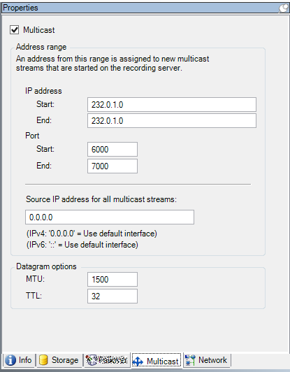
Specify the range you want to assign as addresses for multicast streams from the selected recording server. The clients connect to these addresses when the users view multicast video from the recording server.
For each multicast camera feed, the IP address and port combination must be unique (IPv4 example: 232.0.1.0:6000). You can either use one IP address and many ports, or many IP addresses and fewer ports. By default, the system suggests a single IP address and a range of 1000 ports, but you can change this as required.
IP addresses for multicasting must be within the range defined for dynamic host allocation by IANA. IANA is the authority overseeing global IP address allocation.
|
Name |
Description |
|---|---|
| IP address |
In the Start field, specify the first IP address in the required range. Then specify the last IP address in the range in the End field. |
| Port |
In the Start field, specify the first port number in the required range. Then specify the last port number in the range in the End field. |
| Source IP address for all multicast streams |
You can only multicast on one network interface card, so this field is relevant if your recording server has more than one network interface card or if it has a network interface card with more than one IP address. To use the recording server's default interface, leave the value 0.0.0.0 (IPv4) or :: (IPv6) in the field. If you want to use another network interface card, or a different IP address on the same network interface card, specify the IP address of the required interface.
|
Specify the settings for data packets (datagrams) transmitted through multicasting.
|
Name |
Description |
|---|---|
| MTU |
Maximum Transmission Unit, the largest allowed physical data packet size (measured in bytes). Messages larger than the specified MTU are split into smaller packets before they are sent. The default value is 1500, which is also the default on most Windows computers and Ethernet networks. |
| TTL |
Time To Live, the largest allowed number of hops a data packet should be able to travel before it is discarded or returned. A hop is a point between two network devices, typically a router. Default value is 128. |
Network tab (recording server)
If you need to access the VMS with XProtect Smart Client over a public or untrusted network, Milestone recommends that you use a secure connection through VPN. This helps ensure that communication between XProtect Smart Client and the VMS server is protected.
You define a recording server's public IP address on the Network tab.
Clients may connect from the local network as well as from the Internet, and in both cases the surveillance system must provide suitable addresses so the clients can get access to live and recorded video from the recording servers:
- When clients connect locally, the surveillance system should reply with local addresses and port numbers
- When clients connect from the internet, the surveillance system should reply with the recording server's public address. This is the address of the firewall or NAT (Network Address Translation) router, and often also a different port number. The address and the port can then be forwarded to the server's local address and port.


