Creating smart maps
Before you can take advantage of smart map features, you must complete a few configuration tasks in XProtect Smart Client. You can only view a smart map if it has been added to a view.
See also Add smart maps to views. For more information, see Smart Maps.
Differences between maps and smart maps
XProtect Smart Client includes map features that can help you visualize your surveillance system and quickly respond to incidents.
- Maps: this type of map is based on still images that do not contain geographical references. You can add devices such as cameras, microphones, and recording servers. You can also add alarms, events, and access controls that let you interact with your surveillance system directly from the map. You must manually position device and feature elements on the map. For more information, see Maps.
- Smart map: this type of map uses a geographic information system to accurately reflect geography in the real world. These advanced features can give you a more exact overview of your cameras in multiple locations.
You can also:
- Use the Bing Maps and the Google Maps services (available in XProtect® Corporate and XProtect Expert only.)
- Use the Milestone Map Service as geographic backgrounds.
- Use the OpenStreetMap map project as geographic backgrounds.
- Add computer-aided design (CAD) drawings, shapefiles, and images as overlays (CAD files are available in XProtect® Corporate and XProtect Expert only.)
Maps and smart maps are not interchangeable. If you are using maps, you can use the image file as a smart map, but you must add the devices again. You cannot transfer maps with devices to a smart map but you can link a smart map to maps. For more information, see Adding, deleting, or editing links on smart map.
Add smart maps to views
By default, the basic world map is displayed. When you add smart maps, you can change the geographical background.
To add a smart map![]() A map functionality that uses a geographic information system to visualize devices (for example, cameras and microphones), structures, and topographical elements of a surveillance system in geographically accurate, real-world imagery. Maps that use elements of this functionality are called smart maps., you must add it to a view:
A map functionality that uses a geographic information system to visualize devices (for example, cameras and microphones), structures, and topographical elements of a surveillance system in geographically accurate, real-world imagery. Maps that use elements of this functionality are called smart maps., you must add it to a view:
- In live or playback mode, select the view that you want to add to the smart map.
-
On the workspace toolbar, select Setup.
- Expand the System overview pane, and then drag the Smart map item to the relevant position within the view.
-
Select Setup again to exit setup mode and save your changes.
Now you can change the geographic background.
Change geographic backgrounds on smart maps
By default, the basic world map displays when you add a smart map to a view. After you have added the smart map to a view, you can select a different geographic background. Every user who uses the smart map sees the new background the next time that they display this view.
Geographic backgrounds from Bing Maps and Google Maps are available only in XProtect® Corporate and XProtect Expert. Your system administrator must also make them available in XProtect Management Client.
To change the background:
- Select the view that contains the smart map.
- In the toolbar, click
 Show or hide layers and custom overlays.
 - Under Geographic backgrounds, select the background and the type of detail that you want to display. For example, if you want to see topographical information, select Terrain. If you want to see roads, select Road.
Geographic backgrounds
You can use the following services as the geographic backgrounds of your smart map![]() A map functionality that uses a geographic information system to visualize devices (for example, cameras and microphones), structures, and topographical elements of a surveillance system in geographically accurate, real-world imagery. Maps that use elements of this functionality are called smart maps.:
A map functionality that uses a geographic information system to visualize devices (for example, cameras and microphones), structures, and topographical elements of a surveillance system in geographically accurate, real-world imagery. Maps that use elements of this functionality are called smart maps.:
-
Bing Maps
-
Google Maps
-
Milestone Map Service
-
OpenStreetMap
After you have selected the geographic background, you can add the devices, for example cameras, and custom overlays, for example shapefiles. For more information, see Custom overlays.
Types of geographic backgrounds
After you have added a smart map![]() A map functionality that uses a geographic information system to visualize devices (for example, cameras and microphones), structures, and topographical elements of a surveillance system in geographically accurate, real-world imagery. Maps that use elements of this functionality are called smart maps. to a view, you can use one of the following geographic backgrounds:
A map functionality that uses a geographic information system to visualize devices (for example, cameras and microphones), structures, and topographical elements of a surveillance system in geographically accurate, real-world imagery. Maps that use elements of this functionality are called smart maps. to a view, you can use one of the following geographic backgrounds:
- Basic world map: use the default geographic background provided in XProtect Smart Client. This map is intended for use as a general reference, and it does not contain features such as country boundaries, cities, or other details. However, like the other geographic backgrounds, it does contain geo-reference data
- Bing Maps: connect to Bing Maps
- Google Maps: connect to Google Maps
Bing Maps and Google Maps are available in XProtect® Corporate and XProtect Expert only. The use of both services requires internet access.
- Milestone Map Service - connect to a free map provider. After you enable Milestone Map Service, no further setup is needed.
-
OpenStreetMap - connect to:
- A commercial tile server of your own choice
-
Your own, online or local tile server
- None - this option hides the geographic background. Note that the geo-reference data remains there. See also Layers on smart map
By default, Bing Maps and Google Maps display satellite imagery. You can change the imagery, for example to aerial or terrain, to see different details.
Enable Milestone Map Service
Milestone Map Service is an online service with which you can connect to a tile server of Milestone Systems. This tile server uses a free, commercially available map service.
After you enable Milestone Map Service on your smart map, the smart map uses Milestone Map Service as its geographic background.
If the Milestone Map Service field is grayed out, you don't have the necessary user permissions to enable or disable the service. Contact your system administrator to help you enable the feature in XProtect Management Client.
Milestone Map Service requires internet access.
Steps:
-
On the global toolbar, select Settings and more
 and then Settings
  .
.
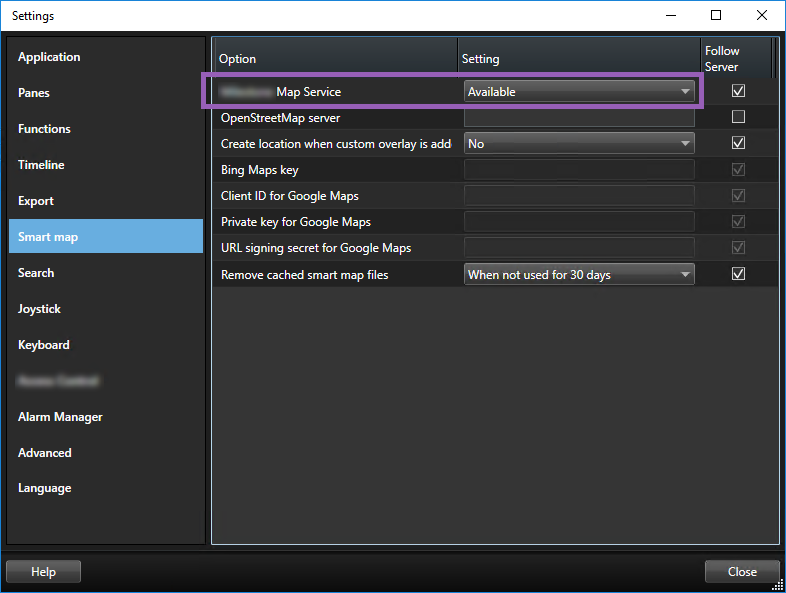
- In the left section, click Smart map.
- In the Milestone Map Service field, select Available.
- Click Close. Next time you load your smart map, it uses Milestone Map Service as the geographic background.
OpenStreetMap tile server
If you use OpenStreetMap as the geographic background for your smart map, you need to specify a tile server. You can specify a local tile server, for example if your organization has its own maps for areas such as airports or harbors, or you can use a commercial tile server.
To use a local tile server, you do not need internet access.
The tile server address can be specified in two ways:
- In XProtect Management Client - you set the tile server address on the Smart Client profiles. The server address applies to all XProtect Smart Client users assigned to the Smart Client profiles
- In XProtect Smart Client - you set the tile server address in the Settings dialog. The server address applies only to that installation
Change OpenStreetMap tile server
If the tile server specified server-side has been locked for editing, the field is grayed out and you cannot change the server address. Contact your system administrator to help you enable the feature in XProtect Management Client.
Steps:
-
On the global toolbar, select Settings and more
 and then Settings
  .
.
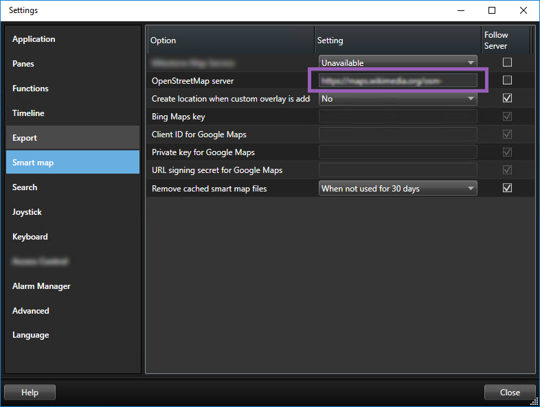
- In the left section, click Smart map.
- In the OpenStreetMap server field, do one of the following:
- Enter the server address. If the field is grayed out, it has been locked server-side
- To use the server specified server-side, if any, select the Follow server check box
- Click Close. Next time you load your smart map, it will use the OpenStreetMap server that you have specified.
If no server address is specified, or the server address is invalid, then OpenStreetMap is not available as a geographic background.
Showing or hiding layers on smart map
You can turn layers on and off on your smart map depending on what you want to see.
Layers on smart map
A smart map has multiple layers. Each layer contains different elements.
You can hide the elements on a smart map layer. This feature is useful when you want to focus on a specific element or simplify the display on the smart map.
| Layer | Elements |
|---|---|
| System elements | Cameras and other devices. Links and locations. |
| Custom overlays | Bitmap images, CAD drawings, and shapefiles. |
| Geographic backgrounds | The basic world map or one of the following services:
|
Bing Maps and Google Maps are available as geographic backgrounds only if your system administrator has enabled them in XProtect Management Client. For more information, see Geographic backgrounds.
Order of layers
All system elements of each type are on the same layer![]() The geographic background on a smart map, a custom overlay, or a system element, for example a camera. Layers are all the graphic elements that exist on the smart map.. For example, all cameras are on the same layer. If you hide the camera layer, all cameras are hidden. From top to bottom, layers for system elements are arranged in the following order: locations, cameras, links, and geographic background. You cannot change this order.
The geographic background on a smart map, a custom overlay, or a system element, for example a camera. Layers are all the graphic elements that exist on the smart map.. For example, all cameras are on the same layer. If you hide the camera layer, all cameras are hidden. From top to bottom, layers for system elements are arranged in the following order: locations, cameras, links, and geographic background. You cannot change this order.
The geographic background is always the lowest layer on a smart map. You can switch between geographic backgrounds, but you can select only one geographic background at a time.
Custom overlays are added as separate layers, and are stacked in the order in which they were added to the smart map. You rearrange the order by configuring default settings for the map.
A city planner has a shapefile that shows the city boundaries, and a shapefile that includes all major roads within the city. The planner can arrange the order of layers so that the roads display on top of the city boundaries. This gives a general view of where cameras are in the city, and the ability to zoom in to see the name of the street that a particular camera is on.
Show or hide layers on smart map
You can show or hide layers on your smart map, including the geographical background. This is useful, for example, when you want to focus on a specific element on the smart map, or just simplify what is shown on the smart map.
-
Select your smart map.
-
On the toolbar, select
 Show or hide layers and custom overlays.
 -
To show or hide the System elements and Custom overlays layers, select or clear the check boxes.
Hiding the System elements layer mutes all microphones until you show the layer again. Manually muted microphones remains muted.
-
To hide the Geographic background layer, select None.
Even if the geographic background layer is hidden, the geo-references still apply to the smart map.
Even if the geographic background is hidden, if you, for example, add a new shapefile that contains spatial reference, the system still uses the spatial reference to place the file correctly on the map.
Specify default settings for smart map
After adding a smart map to a view, and you have added the overlays, cameras, and links, you can specify the default settings for the custom overlays. You can also delete custom overlays to clean up.
Steps:
- Click Setup.
- Click
 Manage default settings.
 - Do any of the following:
- To show or hide an overlay, select or clear the check box
- To rearrange the order, use the drag handle in front of the overlay to drag it to a new position in the list. Layers are ordered from top to bottom in the list
- To delete an overlay, hover the pointer over the overlay, and then click Delete
- Click Save.
Adding, deleting, or editing custom overlays
Custom overlays
You can add the following types of files as custom overlays on a smart map in XProtect Smart Client:
- Shapefile - can contain geo-spatial vector data, such as points, lines, polygons, and attributes that represent objects on a map, such as walls, roads, or geographical features like rivers or lakes. For example, city planning and administration offices often use shapefiles because they scale well when you zoom in and out, and their file size is often smaller than CAD drawings or bitmap images
- CAD - a computer-aided design (CAD) drawing is useful as an overlay because, like shapefiles, CAD data can use a coordinate system and spatial reference to provide accurate geographical context. For example, you can use a detailed ariel map or a road map of a location
- Image - if you have an image file, such as the floor plan of a building, you can add it as an overlay on the smart map. You can use the following types of image files: PNG, BMP, GIF, JPG, JPEG, PHG, TIF, and TIFF
To put custom overlays into focus, you can temporarily hide other types of layers. See Layers on smart map.
Custom overlays and locations
You can quickly jump to custom overlays that you have added to your smart map as described in Go to a custom overlay on your smart map. However, in the settings, you can establish a connection between custom overlays and locations. This means that whenever you add a new custom overlay, XProtect Smart Client creates a location with the same name as the overlay on the exact same spot on the map. The location of the custom overlay now becomes available in the Select a location list.
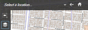
The overlay and location are not linked. For example, you can delete or rename the location without changing the overlay, and vice versa.
To turn on this feature, see Add locations to custom overlays (smart map).
Add custom overlay on smart map
Increase the level of detail on your smart map by adding custom overlays. When you add a custom overlay![]() A user-defined, graphic element that users can add to a smart map, for example to illustrate a floor plan in a building, or to mark borders between regions. A custom overlay can be an image, a CAD drawing, or a shapefile., XProtect Smart Client creates a location with the same name as the overlay.
A user-defined, graphic element that users can add to a smart map, for example to illustrate a floor plan in a building, or to mark borders between regions. A custom overlay can be an image, a CAD drawing, or a shapefile., XProtect Smart Client creates a location with the same name as the overlay.
Steps:
- Select the view that contains the smart map, and then click Setup.
- Click
 Add a custom overlay:
- If the overlay is geo-referenced, click anywhere on the smart map. XProtect Smart Client uses the geo-reference information to place the overlay in the correct geographic location. Additionally, the smart map will center on the overlay at a default zoom level
- If the overlay is not geo-referenced, go to the point on the map where you want to add the element, and then click the point on the smart map
Before you add an overlay, it's a good idea to zoom in to the place on the map where you want to put it. This makes it easier to accurately position the overlay.
- Enter a name for the overlay.
- Depending on the file type you select:
- Image - select the image file, and then click OK
- Shapefile - select the SHP file. If you have a PRJ file, XProtect Smart Client will find it, and you can just click OK. If you do not have a PRJ file, you can reposition the overlay manually after you add it. You can also apply fill- and line colors. Adding colors can make the shapefile stand out more on the smart map
- CAD - select the DWG file. If you have a PRJ file, click OK. If you do not have a PRJ file, and you want to use geo-referencing to position the file on the smart map, enter the spatial reference identifier (SRID), and then click OK. If you do not have a PRJ file or an SRID, you can reposition the overlay manually after you add it
For more information about the types of overlays, see Custom overlays.
Add locations to custom overlays (smart map)
You can configure XProtect Smart Client to automatically add locations to custom overlays![]() A user-defined, graphic element that users can add to a smart map, for example to illustrate a floor plan in a building, or to mark borders between regions. A custom overlay can be an image, a CAD drawing, or a shapefile. on your smart map. This allows you to jump to the custom overlays through the Select a location list.
A user-defined, graphic element that users can add to a smart map, for example to illustrate a floor plan in a building, or to mark borders between regions. A custom overlay can be an image, a CAD drawing, or a shapefile. on your smart map. This allows you to jump to the custom overlays through the Select a location list.
Steps:
-
On the global toolbar, select Settings and more
 and then Settings
  .
.
- Go to the Smart map tab.
- In the Create location when layer is added list, select Yes.
- Close the dialog to save the changes.
For more information, see Custom overlays and locations.
Delete custom overlay on smart map
- Select the view that contains the smart map, and then click Setup.
- In the toolbar, click
 Manage default settings.
 - Hover the pointer over the custom overlay, and then click Delete.
- Click Save to delete the custom overlay.
- Optional: If a location was created for the custom overlay, you might want to delete that as well. For more information, see Adding, deleting, or editing locations on smart map.
Make areas in shapefiles more visible (smart map)
This topic is relevant only if you are using shapefiles with polygons.
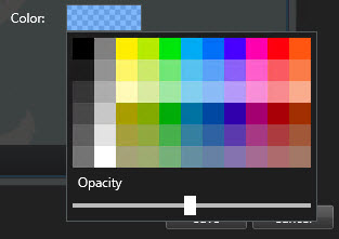
If you want to use a shapefile on your smart map that consists of polygons in close proximity, you may need to distinguish the individual polygons from each other. You do that by decreasing the opacity of the color you pick for the shapefile. The borders of the polygons will stand out.
Steps:
- Follow the steps described in Add custom overlay on smart map.
-
When selecting the color, drag the Opacity slider to the left until you are ok with the level of transparency.
- Click Save.
Adjust position, size, or alignment of custom overlay
You can move an overlay to a different place on the map, make it larger or smaller, and rotate it. For example, this is useful if your overlay is not geo-referenced, or the overlay is geo-referenced but for some reason does not align exactly with the geographic background.
Steps:
- Select the view that contains the smart map, and then click Setup.
- Right-click the overlay, and select Edit position.
- To resize or rotate the overlay:
- Click and drag a corner handle
- To rotate the overlay around a specific point, move the pivot point to that place on the map. Then click and drag a corner handle
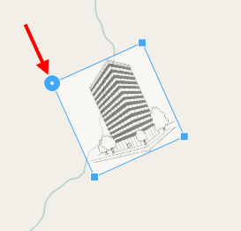
- To move the overlay on the map, click and drag the overlay.
- To save the change, click Save.
Adding, deleting, or editing devices on smart map
You can add devices to a smart map in their actual positions in your environment. This gives you a good overview of your surveillance system, and can help you respond to a situation. For example, if you want to follow a suspect during an ongoing incident, you can click the cameras on the map to view their footage.
After you add a camera to a smart map, you can adjust the field of view for the camera icon so that it reflects the field of view of the actual camera. This makes it easy to find the camera that is covering a particular area. Additionally, you can select an icon to represent the camera on the map, which can help you identify the type of camera on the map.
You can work with the following device types on smart maps:
- Cameras
- Input devices
- Output devices
- Microphones
Add devices to smart map
If the geo-coordinates of the device have been specified in XProtect Management Client by your system administrator, the device will automatically be positioned on the smart map when you add it. If not, you must position the device yourself in its exact geographic location.
If your system administrator has specified the geo-coordinates of the device, XProtect Smart Client you can easily find the device on a smart map. Contact your system administrator to enable thisbenefit inXProtect Smart Client.
- Select the view that contains the smart map, and then click Setup.
- To add a device or a group of devices:
Before you add the device, it's a good idea to zoom in to the location on the map. This makes it easier to accurately position the device if the device has no geo-coordinates.
- Expand the System overview pane, find the device or device group, and then drag it to the point on the smart map where you want to display it. You can drag devices afterward to reposition them
- On the smart map toolbar, select
 Add a device > select the device type.
- Example: In the case of a camera, select
 Add a camera, and then select the camera.
- Example: In the case of a camera, select
- Drag the device to the smart map
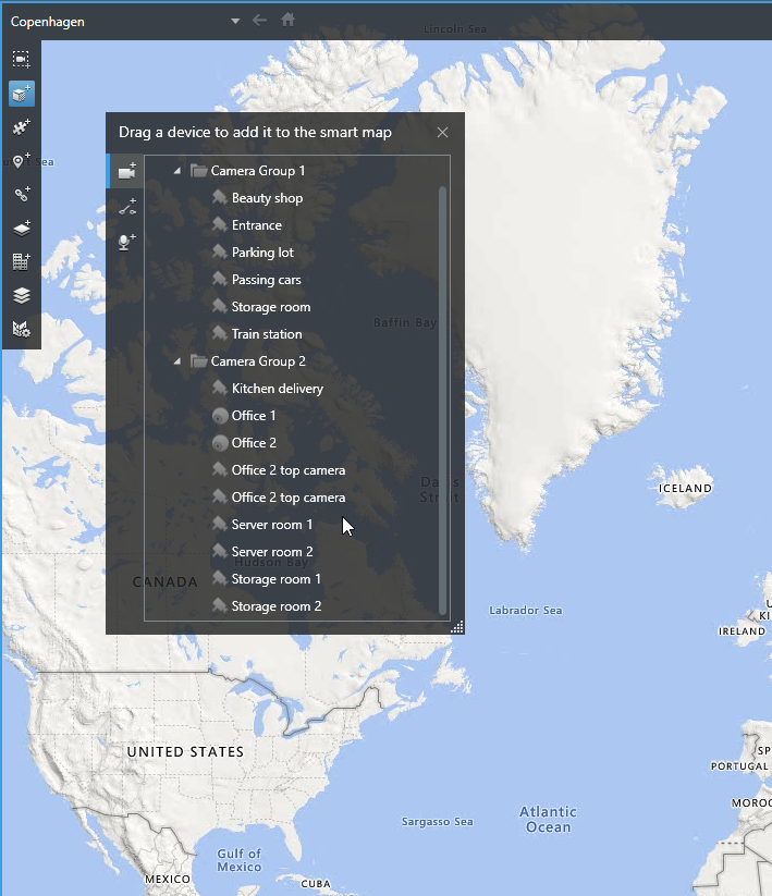
- To save the change, click Setup to exit setup mode.
Change field of view and direction of camera
Once the camera has been added to the smart map, you can change field of view and direction by adjusting the camera icon.
If you are zoomed out on the map, you may have to zoom in until the field of view is displayed.
- Select the view that contains the smart map that you want to work with.
- Click Setup to edit the camera icon.
-
Click the camera icon.
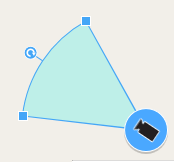
- Use the rotate handle to point the camera in the right direction.
- To adjust the width, length, and angle of the field of view, click and drag the handles at the front edge of the field of view.
- To save your changes, click Setup to exit setup mode.
Select or change device icon
You can choose a device icon that matches the type of device that you are using.
- Select the view that contains the smart map that you want to work with.
-
Click Setup, and then double-click the device icon on the map.
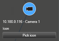
- Click Pick icon, and then select the icon for the device.
- Click Setup again to save the change.
Show or hide device information
You can show or hide information about devices on a smart map. This is useful, for example, when you want to increase or reduce the amount of content on your smart map.
- Select the view that contains the smart map that you want to work with.
- Click
 Show or hide layers and custom overlays.
 - Select or clear the check boxes for the information to show or hide.
Remove devices from smart map
You can remove devices, for example if devices have been physically removed or were added by mistake. By removing a device, the positioning information of the device, for example the geo coordinates, are removed from your VMS system.
These user permissions must be enabled in XProtect Management Client:
- Editing of smart maps
- Editing of devices
Steps:
- Navigate to the device that you want to remove.
- On the workspace toolbar, select Setup.
-
To remove a single device, right-click the device and click Remove.
Example: In the case of a camera, click Remove camera.
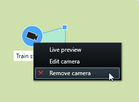
- To remove several cameras:
On the smart map toolbar, click
 Select multiple cameras.
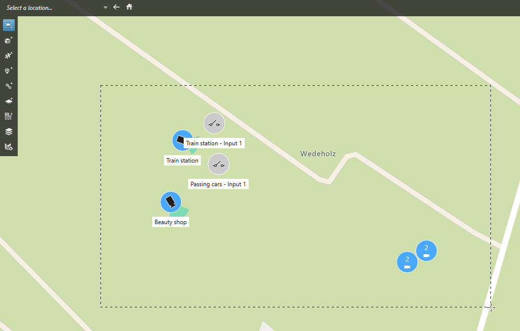
- Click and drag to select multiple cameras. Other types of devices, for example input devices, are not included in the selection.
- Right-click and select Remove cameras.
- To remove several devices that are not cameras:
- On the smart map, press and hold Ctrl.
- While holding down Ctrl, click the devices that you want to remove.
- Right-click one of the selected devices and select Remove.
- Select Setup again to exit setup mode and save your changes.
You can also delete a single device by selecting it and then pressing DELETE on your keyboard.
Adding, deleting, or editing links on smart map
Links on smart map
You can add links that go to locations on your smart map, or go to the static maps in XProtect Smart Client. This lets you quickly visit locations, or display another type of map without changing to another view. You cannot link to another smart map. For more information, see Differences between maps and smart maps.
Links display locations and maps as follows:
- A link to a location displays the location in the current view. To return to a location that you previously viewed, click
 Back on the smart map toolbar
 - A link to a map displays the map in a detached window. This lets you access both types of maps at the same time. You can view and interact with the map but you cannot make changes in the detached window, such as adding cameras
If you color code links, or want to make them more visible on the map, you can specify a color for the link. By default, links to smart map locations are blue, and links to legacy maps are red. If you use a different color, it is a good idea to use the same color for each type of link. For example, this can make it easier to distinguish between links when you use layers to filter items on the map.
Add link to smart map location or map
Adding links to your smart map lets you quickly visit locations, or display another type of map without changing to another view.
Steps:
- Select the view that contains the smart map, and then click Setup.
- Go to the point on the map where you want to add the link.
- In the map toolbar, click
 Add a link, and then click the point on the map where you want the link to be.
 - Specify whether you want to link to a smart map location, or a map, and then click Add.
-
Enter a name for the link.
You can display the title of the link on the smart map if you select Icon and text as the display style. Typically, names indicate where the link takes you.
- In the Destination field, select the map or location that the link goes to.
- In the Display style field, specify whether to display the name and link icon, or only the link icon on the map.
- Optional: Click Color to specify a color for your link.
Edit or delete link on smart map
Once you have added a link on your smart map, you can edit or delete it.
Steps:
-
On the workspace toolbar, select Setup.
- To edit the link, right-click the link and select Edit link.
- To delete the link, do one of the following:
- Right-click the link and select Delete link
- Select the link and press DELETE on your keyboard
Adding, deleting, or editing locations on smart map
Locations on smart map
You can create locations at the points on the smart map that are of interest to you. For example, you can create locations for your home office, and satellite offices. Not only do locations give you a full picture of your environment, they are also useful for navigating the smart map.
Depending on your configuration, when you add a custom overlay, XProtect Smart Client may add a location with the same name as the overlay. For example, this makes it easier to go to the overlay on the smart map when you are zoomed out. The overlay and location are not, however, linked. For example, you can delete or rename the location without changing the overlay, and vice versa. For more information, see Adding, deleting, or editing custom overlays.
Home locations for smart map
Home locations are specific to the view item they are set in. You can have different home locations in different view items. If a home location is not specified for a view item, the view item displays the whole world, regardless of the type of background you are using. This is also the case if you delete the home location.
While you are working with the smart map, you can click ![]() Home to return to the home location. This is similar to resetting the smart map in the view. You return to the default settings for the view item, and the system deletes the history of the locations you visited.
Home to return to the home location. This is similar to resetting the smart map in the view. You return to the default settings for the view item, and the system deletes the history of the locations you visited.
Selecting a new home location affects everyone who uses the view item. If someone else had set another location as home, you are changing their setting.
Add location to smart map
To keep track of the places that are of interest to you, you can add locations that allow you to quickly navigate to those places on the smart map.
Steps:
- Select the view that contains the smart map, and click Setup.
- If needed, pan and zoom in to the point on the smart map where you want to add the location.
- In the toolbar, click
 Add a location, and then click the point on the smart map.
 - Give the location a name, and then add the following optional details:
- Specify a zoom level to apply when someone goes to the location on the smart map
- Select a color for the location icon. Color-coding locations is useful, for example, for distinguishing between types of locations. This could be based on the function of the location or its type, or indicate the location's priority
- Optional: Make the location your home location. The smart map centers on this location, and applies the default zoom level setting for it, when you click
 Home
Home
Edit or delete location on smart map
Once you have added locations on your smart map, you can delete them or edit the settings, for example deleting the home location.
Steps:
- On the workspace toolbar, select Setup.
- To edit a location, right-click the location and select Edit location.
- To delete a location, do one of the following:
- Right-click the location and select Delete location
- Select the location and press DELETE on your keyboard
Linking between locations
For example, you can create a patrol route by creating a series of links between locations. Create a link at location A that goes to location B, and a link at location B that goes to location C, and so on. For more information, see Adding, deleting, or editing links on smart map.
Adding, deleting, or editing buildings on smart map
Buildings on smart map
Buildings on the smart map![]() A map functionality that uses a geographic information system to visualize devices (for example, cameras and microphones), structures, and topographical elements of a surveillance system in geographically accurate, real-world imagery. Maps that use elements of this functionality are called smart maps. are depicted as polygons with four edges. Once added, you can adjust the dimensions, angles, and size to match the actual shape and position of the building.
A map functionality that uses a geographic information system to visualize devices (for example, cameras and microphones), structures, and topographical elements of a surveillance system in geographically accurate, real-world imagery. Maps that use elements of this functionality are called smart maps. are depicted as polygons with four edges. Once added, you can adjust the dimensions, angles, and size to match the actual shape and position of the building.
If the building is a multistory building, you can start adding levels and add cameras to the individual levels. This allows you to navigate the cameras inside the building, level by level.
To help you illustrate the interior of a level, you can add custom overlays to levels, for example an image illustrating a floor plan. For more information, see Add floor plans to levels (smart map).
Buildings are automatically given a name, for example Building 4. Milestone recommends that you change the name. This makes it easier for you to distinguish buildings from one another.
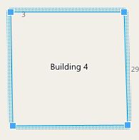
Add buildings to smart map
Instead of using images or shapefiles to illustrate buildings, you can add an outline of a building. Afterwards, you can change the dimensions, angles, and size to match the shape and position of the actual building.
Smart map editing has been enabled on your Smart Client profile in XProtect Management Client.
Steps:
- On the workspace toolbar, select Setup.
- Navigate to the place on the smart map, where you want to position the building.
- Click
 and place the cursor in the relevant position on the smart map.
 - Click again. A rectangle is added to the smart map. If zoomed out, the zoom level automatically increases.
- If necessary, use the corner handles to adjust the shape and position of the actual building.
- Select Setup again to exit setup mode and save your changes.
Edit buildings on smart map
Once a building has been added to the smart map, you can change the name of the building, and adjust the position, the size, dimensions, and angles. You can also add, remove, or reorder levels.
Smart map editing has been enabled on your Smart Client profile in XProtect Management Client.
Steps:
- Navigate to the building on your smart map. If necessary, zoom in.
- On the workspace toolbar, select Setup.
-
Click anywhere inside the building. A blue-ridged border indicates that you can edit the building.

- To rename the building, go to the top of the right-side pane and click
 . Change the name and click
  . To cancel, press Esc.
 - To adjust the corners, click and drag them to a new position.
- To add or remove levels, see Add or remove levels from buildings.
- Select Setup again to exit setup mode and save your changes.
Delete buildings on smart map
If a building is no longer needed, you can delete it. Next time someone logs into XProtect Smart Client or reloads, the building is gone.
Smart map editing has been enabled on your Smart Client profile in XProtect Management Client.
Steps:
- Open the smart map.
- On the workspace toolbar, select Setup.
- Do one of the following:
- Right-click the building and select Delete
- Select the building, and press DELETE on your keyboard
An alternate way of deleting a building: In the ![]() Manage default settings, scroll down to the Buildings section, hover on the building, click Delete and then Save.
Manage default settings, scroll down to the Buildings section, hover on the building, click Delete and then Save.
Managing levels and devices in buildings (smart map)
Devices and levels in buildings
When you add a device to a building, by default, the device is associated with the default level if one has been specified. Otherwise, the device is assigned to the first level. However, you can change this and associate the device with any other level, or several levels at the same time.
More facts:
- If no levels are selected, the device is visible on all levels
- If you add a building on top of a device that is already positioned, by default, the device is associated with all levels
- If you expand the boundaries of a building so that it covers a device that is already positioned, the device is associated only with the level that is selected
If you readjust the boundaries of the building so that it no longer covers the device, the device is no longer associated with the building.
Floor plans and devices in buildings
To help you visualize the interior of the levels in a building, you can add floor plans as custom overlays. With a floor plan in place, it is easier to precisely position the device. For more information, see Add floor plans to levels (smart map).
The devices that you position are associated with levels, not custom overlays. If you delete a level inside a building with devices and a custom overlay, the devices stay in their geographical position, but are no longer associated with the level. However, the custom overlay is deleted together with the level.
If you reorder a level, both the devices and the custom overlay stay with the level. The devices maintain their geographical position.
Add or remove levels from buildings
After adding a building to your smart map, you can add any number of levels. The first level is assigned the number 1, the next 2, and so forth. Afterwards, you can rename and reorder the individual levels.
Smart map editing has been enabled on your Smart Client profile in XProtect Management Client.
Steps:
- Navigate to the building on your smart map. If necessary, zoom in.
- Select the building. A pane appears on the right-hand side.
- Click the Setup button to enter setup mode.
- Click Add level
 .
. - To edit the level name:
- Click the dots
 and select Rename.
 - Enter a new name.
- Click the dots
- To delete a level, click the dots
 and select Delete. Devices on this level stay in their geographical position, but they are no longer associated with the level.
 - Click Setup to exit setup mode.
Change order of levels in buildings (smart map)
Smart map editing has been enabled on your Smart Client profile in XProtect Management Client.
Steps:
- Navigate to the building on your smart map. If necessary, zoom in.
- Select the building. A pane appears on the right-hand side showing you the levels of the building.
- On the workspace toolbar, select Setup.
- Click and drag the dotted area
 to the correct position. Any associated devices and custom overlays stay with the level.
 - Select Setup again to exit setup mode and save your changes.
Set default level for buildings (smart map)
If a particular level in a building is more relevant than others, for example the ground floor, you can set that level as the default level. When you open your smart map and go to the building, automatically the default level is selected.
If you navigate away from the building and back, XProtect Smart Client brings you to the level where you left off.
Smart map editing has been enabled on your Smart Client profile in XProtect Management Client.
Steps:
- Navigate to the building on your smart map. If necessary, zoom in.
- Select the building. A pane appears on the right-hand side showing you the levels of the building. The default level is highlighted.
- Click Setup to enter setup mode. Notice the asterisk
 . It indicates where the current default level is.
 - On the level you want to set as the default level, click the dots
 .
. - Select Set as default.
- Select Setup again to exit setup mode and save your changes.
Add floor plans to levels (smart map)
You can add custom overlays, for example floor plan images, to the levels in your building to help you illustrate the interior of a level inside a building. As you navigate the levels, automatically the associated floor plans are displayed.
Smart map editing has been enabled on your Smart Client profile in XProtect Management Client.
Steps:
- Navigate to the building on your smart map. If necessary, zoom in.
- Select the building. A pane appears on the right-hand side showing you the levels of the building.
- On the workspace toolbar, select Setup.
- Select the level where you want to add the custom overlay.
- In the upper left corner, click
 Add a custom overlay, and then click anywhere inside the building outline. A window appears.
 - Select the type of custom overlay. For more information, see Custom overlays.
-
Select the location on your computer where the file is stored and click Continue. The custom overlay is displayed as a blue outline.
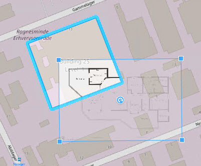
- Drag it onto the outline of the building and use the pivot point and corner handles to rotate and reposition the custom overlay.
- In the bar at the top, click Save.
- Select Setup again to exit setup mode and save your changes.
Delete floor plans on levels (smart map)
If a floor plan on a level inside a building has changed, you may need to replace the custom overlay illustrating the floor plan. Milestone recommends that you delete the old floor plan, before adding a new one.
Smart map editing has been enabled on your Smart Client profile in XProtect Management Client.
Steps:
- Navigate to the building on your smart map. If necessary, zoom in.
- Select the building. A pane appears on the right-hand side showing you the levels of the building.
- On the workspace toolbar, select Setup.
- Select the level where the custom overlay is.
- Right-click anywhere on the custom overlay and select Delete custom overlay.
- Select Setup again to exit setup mode and save your changes.
To edit the position or size of the floor plan, right-click the custom overlay and select Edit position. Now you can move, rotate, and change the size of the custom overlay.
Add devices to buildings (smart map)
After creating a building and adding levels, you can add devices to the building. If you've specified a default level, the devices are associated with it. If not, the devices are associated with the first level. You can change the level and associate the device with any of the levels in the building.
Smart map editing has been enabled on your Smart Client profile in XProtect Management Client.
Steps:
- Go to the building on your smart map. Zoom in if needed.
- On the workspace toolbar, select Setup.
- To add a device, click its icon.
Example: in the case of a camera, click
 Add a camera.
 - Click again on the location to position the device. A window is displayed.
- Select the device and click OK. For each device to add, repeat steps 3-5.
- To associate a device with one or more levels, right-click the device and select the required levels.
- Select Setup again to exit setup mode and save your changes.
If you haven't selected any level, the device is visible on all levels.

