

System communication and data flow
The following illustrations provide an overview of the flow of data between XProtect components.
For a complete list of the ports that must be enabled for communication between components, see Ports used by the system.
Server communication

-
Management server - Recording server
-
Recording server - Media database
-
Management server - Internal
-
SQL Server database communication
-
Management server - Mobile server
-
Authentication of basic users by the Identity Provider
-
API Gateway - Management server
Login from XProtect Smart Client as an AD user

-
XProtect Smart Client connects to the management server and attempts to log in
-
The management server contacts Active Directory to authenticate the user
-
User-specific configuration is retrieved from the SQL Server database
-
Login is granted and the configuration is sent to XProtect Smart Client
Login from XProtect Smart Client as a basic user

-
XProtect Smart Client attempts to connect to the management server as a basic user
-
The login request goes to the Identity Provider for authentication
-
User-specific configuration is retrieved from the SQL Server database
-
Login is granted and the configuration is sent to XProtect Smart Client
Login from XProtect Smart Client with an external IDP

-
Login from XProtect Smart Client launches a web browser on the client computer.
-
The login request goes from the web browser to the Identity Provider for authentication.
-
The web browser is redirected to the external IDP login page where the user enters credentials and the browser receives an authorization code.
-
The Identity Provider requests information about the user from the external IDP and receives a list of claims. If a new user logs in to the VMS, the user is created in the VMS.
-
The web browser is redirected to XProtect Smart Client with the authorization code from the Identity Provider.
-
XProtect Smart Client gets an access token from the Identity Provider.
-
XProtect Smart Client login to the management server using the access token.
-
Verification of user permissions according to claims to role mapping.
-
The user logs in to XProtect Smart Client upon successful authorization.
Live video and audio

-
Live streams from cameras retrieved by the recording server
-
Streams are sent to XProtect Smart Client on request
Live video multicasting

-
Live streams from cameras retrieved by the recording server
-
Recording server sends multicast stream to the multicast enabled network. This requires that all switches handling the data traffic between the XProtect Smart Client and the recording server must be configured for multicast
-
The multicast stream is received by all XProtect Smart Clients on request
Matrix

-
XProtect Smart Client user selects to send a camera to a Matrix-recipient
-
Information is sent to management server
-
Management server sends request to Matrix-recipient on specified IP address and port (XProtect Smart Client B)
-
Streams are sent to XProtect Smart Client from recording server on request
Management server – view update

-
View updated on XProtect Smart Client
-
The system configuration is stored in the SQL Server database
-
The management server sends notification about view update to XProtect Smart Clients
-
XProtect Smart Clients retrieves and applies the new view
XProtect Smart Wall

-
An XProtect Smart Client user updates the XProtect Smart Wall view
-
The XProtect Smart Wall view configuration is updated and stored in the SQL Server database
-
The management server sends a notification to the XProtect Smart Client running the XProtect Smart Wall
-
The XProtect Smart Client running the XProtect Smart Wall retrieves and applies new layout
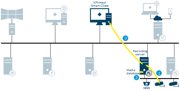
Play back video and audio
-
Recording stream from cameras retrieved by the recording server
-
The stream is recorded in the recording server database based on rules
-
The recorded stream is retrieved by XProtect Smart Client on playback request
Login from XProtect Web Client and XProtect Mobile as an AD user

-
Login request from XProtect Web Client or XProtect Mobile received on the mobile server
-
The mobile server forwards request to the management server
-
The management server contacts Active Directory to authenticate the user
-
User-specific configuration is retrieved from the SQL Server database
-
Information returned to the mobile server
-
The login is granted and configuration is sent to XProtect Web Client or XProtect Mobile
Login from XProtect Web Client and XProtect Mobile as a basic user

-
Login request from XProtect Web Client or XProtect Mobile received on the mobile server
-
The mobile server forwards a request to the management server
-
The login request goes to the Identity Provider for authentication
-
User-specific configuration is retrieved from the SQL Server database
-
Information returned to the mobile server
-
The login is granted and configuration is sent to XProtect Web Client or XProtect Mobile
Login from XProtect Web Client and the XProtect Mobile client with an external IDP

-
In XProtect Web Client or in the XProtect Mobile client, the user selects to log in via an external IDP. The login request launches a web browser.
-
The web browser is redirected to the external IDP login page where the user enters credentials.
-
The Identity Provider receives an authorization code from the external IDP to be exchanged for an access token. Then the Identity Provider requests information about the user from the external IDP and gets a list of claims. If a new user logs in to the VMS, the user is created in the VMS.
-
The Identity Provider returns an authorization code to XProtect Web Client or the XProtect Mobile client.
-
XProtect Web Client or the XProtect Mobile client requests an access token from the Identity Provider.
-
XProtect Web Client or the XProtect Mobile client logs in to the mobile server using the access token.
Live video for XProtect Web Client and XProtect Mobile

-
Live stream(s) from cameras retrieved on the recording server
-
Streams are sent to the mobile server for transcoding or as direct streaming
-
Video is streamed to the clients
Recording and playback video for XProtect Web Client and XProtect Mobile

-
Recording stream from cameras retrieved on the recording server
-
The stream is recorded in the recording server database based on rules
-
Recordings are sent to the mobile server for transcoding or as direct streaming
-
Video is streamed to clients
Video push

-
Video push stream from a device running XProtect Mobile is sent instantly to the mobile server
-
The video push stream is retrieved by recording server using the specific video push device driver
Milestone Interconnect live

Illustrates how XProtect Smart Client users, specified for the interconnected system, only need to log into the management server on the central site to view video.
-
Live stream(s) from the remote site cameras retrieved by the remote site recording server
-
Live streams from the remote site recording server retrieved by the central site recording server
-
Stream(s) are sent to XProtect Smart Client on request
Milestone Interconnect recording options

Some of the different options when configuring your system recording settings:
-
No recording
-
Record at remote site only
-
Retrieve recordings from remote site on request
-
Retrieve recordings from remote site based on rule (time profile)
-
Record at central site only
-
Retrieve recordings from remote site after site link down
-
Record at both sites
-
Combinations of above and other options
Milestone Interconnect play back

Illustrates when recording is done on both sites. Recordings can be retrieved to the central site based on schedule, event or request. XProtect Smart Client users, specified for the interconnected system, only need to log into the management server on the central site to view video.
-
Recording stream from the remote site cameras retrieved by the remote site recording server
-
The stream is recorded in the remote site recording server database based on rules
-
Recording stream from the remote site recording server retrieved by the central site recording server
-
The stream is recorded in the central site recording server database based on rules. Recordings not available due to remote site link downtime can be retrieved automatically or based on schedule, event or request
-
The recorded stream(s) are retrieved by XProtect Smart Client on playback request
XProtect DLNA Server

-
The XProtect DLNA Server connects to the management server to authorize itself with the provided credentials
-
A DLNA device scans the network and connects to the XProtect system via the XProtect DLNA Server and requests a live camera video stream
-
XProtect DLNA Server retrieves the requested camera video stream from the recording server
-
XProtect DLNA Server sends the live video stream from the requested camera to the DLNA device
Milestone Open Network Bridge

-
Login, stream or PTZ request from ONVIF client received on the Milestone Open Network Bridge server. The Milestone Open Network Bridge is a gateway for non-Milestone clients to the Milestone VMS
-
The Milestone Open Network Bridge forwards the login request to the management server to authenticate the user.
Access to the Milestone VMS is granted and sent to the Milestone Open Network Bridge server -
Requested live or playback stream from the recording server is retrieved by the Milestone Open Network Bridge server
-
Video is streamed to the ONVIF client
Management Client configuration update

-
Configuration updated on the Management Client
-
Changes are stored on the management server
-
Configuration update sent to relevant components. In this case, the recording server
-
If updates concern cameras, the recording server applies new settings
Log server

-
The Management server or recording server creates a log message
-
The log message is forwarded to the log server
-
The log message is stored in the log server's SQL Server database
Event server

The event server sends data to XProtect Smart Client to show in alarm list, XProtect Access or the map overview. The event server Plug-in is a client to the access control system.
The XProtect Smart Client user responds to the notification and returns data to event server.
XProtect Transact
![]()
-
Transaction data generated by the transaction source is sent to the event server and stored
-
The event server sends transaction data to XProtect Smart Client. View items containing transaction data and the associated video is updated
XProtect LPR

-
Live streams from cameras configured for LPR (License Plate Recognition) retrieved by the recording server
-
Streams from the recording server retrieved by the LPR server
-
The LPR server recognizes license plates by comparing them with the license plate styles of the installed country modules. Found license plates are compared with the match list requests from the event server LPR plug-in
-
The event server sends events and alarms to XProtect Smart Client when there is a match
View and manage alarms

-
XProtect Smart Client requests an alarm list from event server
-
The alarm list is retrieved from the SQL Server database and returned to XProtect Smart Client
-
The alarm is handled and its state/details is updated by the user
-
New state/details stored in the SQL Server database
Data collector

-
System status received on management server delivered by: log server, event server, recording server, failover recording server and mobile server
-
The collected data is stored in a SQL Server database on SQL Server
-
XProtect Smart Client or the Management Client requests status via System Monitor
-
Requested data is collected from a SQL Server database on SQL Server
-
Data returned to clients
Recording server failover

-
Video streamed from the recording server
-
Alive messages exchanged between recording and failover recording server
-
Cold standby: failover message sent, configuration retrieved, start failover
Hot standby: failover message sent, start failover -
Configuration updated with active failover recording server
-
Update configuration message sent to the management server
-
Update message distributed to all clients
-
Video streamed from failover recording server
Evidence lock

-
The user creates an evidence lock in XProtect Smart Client. XProtect Smart Client sends the information to the management server
-
The management server informs the recording server to store and protect the locked recordings in the Media database
-
The management server stores information about the evidence lock in the SQL Server database
XProtect Incident Manager

| Flow | Actions and components |
|---|---|
| 1 |
An operator of XProtect Smart Client starts, saves, edits, or deletes an incident project. Information about the incident project and its data is saved in the extension’s own SQL Server database Surveillance_IM. The activities related to incident projects are - depending on the activity - logged in the extension’s own SQL Server database Surveillance_IM, in the Log Server service’s SQL Server database SurveillanceLogServerV2, or in both. |
| 2 | A Management Client administrator creates, edits, or deletes an incident property. The incident property definition is saved in the extension’s own SQL Server database Surveillance_IM. The user activity is logged in the Log Server service’s SQL Server database SurveillanceLogServerV2. |
Move hardware

-
The user moves hardware from recording server 1 to recording server 2 in Management Client
-
The management server receives the update in the system configuration and stores it in the SQL Server database
-
The management server sends update to recording server 1
-
The management server sends update to recording server 2
-
Recording server 2 connects to Hardware. All new recordings are stored in the recording server 2 database
Old recordings are still available on recording server 1. The system deletes them when the retention time expires. Recordings marked with evidence lock are not deleted until the evidence lock's retention time expires.
Clients connect to recording server 2