

Site Navigation: Servers and hardware: Recording servers
Recording servers (explained)
The system uses recording servers for recording of video feeds, and for communicating with cameras and other devices. A surveillance system typically consists of several recording servers.
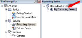
Recording servers are computers where you have installed the Recording Server software, and configured it to communicate with the management server. You can see your recording servers in the Overview pane when you expand the Servers folder and then select Recording Servers.
Backward compatibility with recording server versions older than this version of the management server is limited. You can still access recordings on recording servers with older versions, but if you want to change their configuration, make sure they match this version of the management server. Milestone recommends that you upgrade all recording servers in your system to the same version as your management server.
The recording server supports encryption of data streams to the clients and services. For more information, see Before you start installation:
The recording server also supports encryption of the connection with the management server. For more information, see Before you start installation:
You have several options related to management of your recording servers:
When the Recording Server service is running, it is very important that Windows Explorer or other programs do not access Media Database files or folders associated with your system setup. If they do, it is likely that the recording server cannot rename or move relevant media files. This might bring the recording server to a halt. To restart a stopped recording server, stop the Recording Server service, close the program accessing the relevant media file(s) or folder(s), and restart the Recording Server service.
Register a recording server
When you install a recording server, it is automatically registered in most cases. But you need to do the registration manually if:
- You have replaced the recording server
- The recording server was installed offline and then added to the management server afterward
- Your management server does not use the default ports. The port numbers depend on the encryption configuration. For more information, see Ports used by the system
- An automatic registration has failed, for example after changing the management server address or after enabling or disabling server communication encryption settings
When you register a recording server, you configure it to connect to your management server. The part of the management server that handles registration is the Authorization Server service.
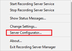
- Open the Server Configurator from either the Windows startup menu or from the recording server tray icon.
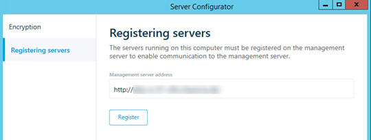
- In the Server Configurator, select Registering servers.
-
Verify the address of the management server and the scheme (http or https) that you want the servers on the computer to connect to and click Register.
A confirmation appears, stating that registration on the management server has succeeded.
See also Replace a recording server.
Change or verify the basic configuration of a recording server
If your Management Client does not list all the recording servers you have installed, the most likely reason is that you have configured the setup parameters (for example, the IP address or host name of the management server) incorrectly during installation.
You do not need to re-install recording servers to specify the parameters of the management servers, but you can change/verify its basic configuration:
- On the computer that runs the recording server, right-click the Recording Server icon in the notification area.
- Select Stop Recording Server service.
- Right-click the Recording Server icon again and select Change Settings.
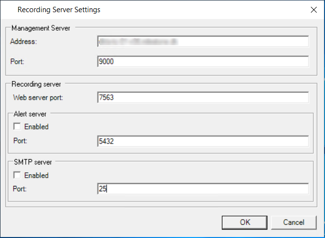
The Recording Server Settings window appears.
- Verify or change, for example, the following settings:
- Management server: Address: Specify the IP address or host name of the management server to which the recording server should be connected.
- Management server: Port: Specify the port number to be used when communicating with the management server. You can change this if required, but the port number must always match the port number set up on the management server. See Ports used by the system.
- Recording server: Web server port: Specify the port number to be used when communicating with the recording server's web server. See Ports used by the system.
- Recording server: Alert server port: Enable and specify the port number to be used when communicating with the recording server's alert server, which listens for event messages from devices. See Ports used by the system.
- SMTP server: Port: Enable and specify the port number to be used when communicating with the recording server's Simple Mail Transfer Protocol (SMTP) service. See Ports used by the system.
- Click OK.
- To start the Recording Server service again, right-click the Recording Server icon, and select Start Recording Server service.
Stopping the Recording Server service means that you cannot record and view live video while you verify/change the recording server's basic configuration.
Recording Server Settings window
When you right-click the Recording Server Manager tray icon and select Change settings, you can specify the following:
|
Name |
Description |
|---|---|
| Address |
IP address (example: 123.123.123.123) or host name (example: ourserver) of the management server to which the recording server should be connected. This information is necessary so that the recording server can communicate with the management server. |
| Port |
Port number to be used when communicating with the management server. Default is port 9000. You can change this if you need to. |
| Web server port |
Port number to be used for handling web server requests, for example for handling PTZ camera control commands and for browse and live requests from XProtect Smart Client. Default is port 7563. You can change this if you need to. |
| Alert server port |
Port number to be used when the recording server listens for TCP information (some devices use TCP for sending event messages). Default is port 5432 (disabled by default). You can change this if you need to. |
| SMTP server port |
Port number to be used when the recording server listens for Simple Mail Transfer Protocol (SMTP) information. SMTP is a standard for sending email messages between servers. Some devices use SMTP for sending event messages or images to the surveillance system server via email. Default is port 25, which you can enable and disable. You can change the port number if you need to. |
| Encrypt connections from the management server to the recording server | Before you enable encryption and select a server authentication certificate from the list, make sure that you enable encryption on the management server first and that the management server certificate is trusted on the recording server. For more information, see Before you start installation |
|
Encrypt connections to clients and services that stream data |
Before you enable encryption and select a server authentication certificate from the list, make sure that the certificate is trusted on all computers running services that retrieve data streams from the recording server. To verify that your recording server uses encryption, see View encryption status to clients. |
|
Details |
|
View encryption status to clients
To verify if your recording server encrypt connections:
- Open the Management Client.
- In the Site Navigation pane, select Servers > Recording Servers. This opens a list of recording servers.
- In the Overview pane, select the relevant recording server and go to the Info tab.
If encryption is enabled to clients and servers that retrieve data streams from the recording server, a padlock icon appears in front of the local web server address and the optional web server address.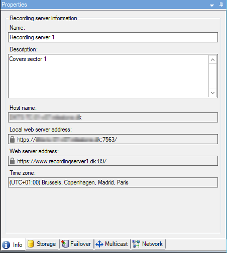
Recording server status icons
Management Client uses the following icons to indicate the state of individual recording servers:
|
Icon |
Description |
|---|---|
|
|
Recording server is running |
|
|
Recording server requires attention: Either the recording server is not running or it is running with errors.
|
|
|
Ongoing database repair: Appears when databases are corrupted, for example due to a power failure, and the recording server is repairing them. The repair process may take some time if the databases are large. See Protect recording databases from corruption for information about how to avoid corrupt databases. During a database repair at startup, you cannot record video from cameras connected to the recording server. Only live viewing is available. A database repair at normal operation does not affect any recordings. |
Info tab (recording server)
On the Info tab, you can verify or edit the name and description of the recording server.
You can view the host name and addresses. The padlock icon in front of the web server address indicates encrypted communication with the clients and services that retrieve data streams from this recording server.
Info tab properties (recording server)
|
Name |
Description |
|---|---|
| Name |
You can choose to enter a name for the recording server. The name is used in the system and clients when the recording server is listed. The name does not have to be unique. When you rename a recording server, the name is changed globally in the Management Client. |
| Description |
You can choose to enter a description that appears in a number of listings within the system. A description is not mandatory. |
| Host name |
Displays the recording server's host name. |
| Local web server address |
Displays the local address of the recording server's web server. You use the local address, for example, for handling PTZ camera control commands, and for handling browsing and live requests from XProtect Smart Client. The address includes the port number that is used for web server communication (typically port 7563). If you enable encryption to clients and servers that retrieve data streams from the recording server, a padlock icon appears, and the address includes https instead of http. |
| Web server address |
Displays the public address of the recording server's web server over the internet. If your installation uses a firewall or NAT router, enter the address of the firewall or NAT router so that clients that access the surveillance system on the internet can connect to the recording server. You specify the public address and port number on the Network tab. If you enable encryption to clients and servers that retrieve data streams from the recording server, a padlock icon appears, and the address includes https instead of http. |
| Time zone |
Displays the time zone that the recording server is located in. |
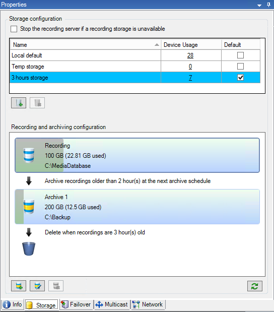
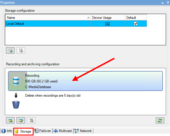
Storage tab (recording server)
On the Storage tab, you can set up, manage and view storages for a selected recording server.
For recording storages and archives, the horizontal bar shows the current amount of free space. You can specify the behavior of the recording server in case recording storages become unavailable. This is mostly relevant if your system includes failover servers.
If you are using Evidence lock, there will be a vertical red line showing the space used for evidence locked footage.
Storage and archiving (explained)
Available functionality depends on the system you are using. See https://www.milestonesys.com/solutions/platform/product-index/ for more information.
When a camera records video or audio, all specified recordings are by default stored in the storage defined for the device. Each storage consists of a recording storage that saves recordings in the recording database Recording. A storage has no default archive(s), but you can create these.
To avoid that the recording database runs full, you can create additional storages (see Add a new storage). You can also create archives (see Create an archive within a storage) within each storage and start an archiving process to store data.
Archiving is the automatic transfer of recordings from, for example, a camera's recording database to another location. In this way, the amount of recordings that you can store is not limited to the size of the recording database. With archiving you can also back up your recordings to another media.
You configure storage and archiving on each recording server.
As long as you store archived recordings locally or on accessible network drives, you can use XProtect Smart Client to view them.
If a disk drive breaks and the recording storage becomes unavailable, the horizontal bar turns red. It is still possible to view live video in XProtect Smart Client, but recording and archiving stops until the disk drive is restored. If your system is configured with failover recording servers, you can specify the recording server to stop running, to let the failover servers take over (see Specify behavior when recording storage is unavailable).
The following mostly mentions cameras and video, but speakers, microphones, audio and sound also apply.
Milestone recommends that you use a dedicated hard disk drive for recording storages and archives to prevent low disk performance. When you format the hard disk, it is important to change its Allocation unit size setting from 4 to 64 kilobytes. This is to significantly improve recording performance of the hard disk. You can read more about allocating unit sizes and find help on the Microsoft website (https://support.microsoft.com/help/140365/default-cluster-size-for-ntfs-fat-and-exfat/).
The oldest data in a database is always auto-archived (or deleted if no next archive is defined) when less than 5GB of space is free. If less than 1GB space is free, data is deleted. A database always requires 250MB of free space. If you reach this limit because data is not deleted fast enough, no more data is written to the database until you free up enough space. The actual maximum size of your database becomes the amount of gigabytes that you specify, minus 5GB.
For FIPS 140-2 compliant systems, with exports and archived media databases from XProtect VMS versions prior to 2017 R1 that are encrypted with non FIPS-compliant cyphers, it is required to archive the data in a location where it can still be accessed after enabling FIPS.
For detailed information on how to configure your XProtect VMS to run in FIPS 140-2 compliant mode, see the FIPS 140-2 compliance section in the hardening guide.Once you have configured the storage and archiving settings for a recording server, you can enable storage and archiving for individual cameras or a group of cameras. You do this from the individual devices or from the device group. See Attach a device or group of devices to a storage.
Effective archivingWhen you enable archiving for a camera or a group of cameras, the content of the recording storage is automatically moved to the first archive at intervals that you define.
Depending on your requirements, you can configure one or more archives for each of your storages. Archives can be located either on the recording server computer itself, or at another location which can be reached by the system, for example on a network drive.
By setting up your archiving in an effective way, you can optimize storage needs. Often, you want to make archived recordings take up as little space as possible especially on a long-term basis, where it is perhaps even possible to slacken image quality a bit. You handle effective archiving from the Storage tab of a recording server by adjusting several interdependent settings:
- Recording storage retention
- Recording storage size
- Archive retention
- Archive size
- Archive schedule
- Encryption
- Frames Per Second (FPS).
The size fields define the size of the recording storage, exemplified by the cylinder, and its archive(s) respectively:
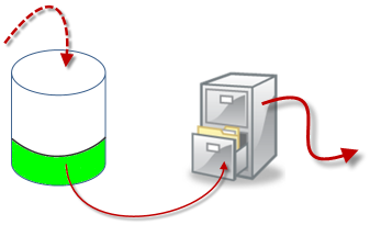
By means of retention time and size setting for the recording storage, exemplified by the white area in the cylinder, you define how old recordings must be before they are archived. In our illustrated example, you archive the recordings when they are old enough to be archived.
The retention time and size setting for archives define how long the recordings remain in the archive. Recordings remain in the archive for the time specified, or until the archive has reached the specified size limit. When these settings are met, the system begins to overwrite old recordings in the archive.
The archiving schedule defines how often and at what times archiving takes place.
FPS determines the size of the data in the databases.
To archive your recordings, you must set all these parameters up in accordance with each other. This means that the retention period of the next archive must always be longer than the retention period of a current archive or recording database. This is because the number of retention days stated for an archive includes all retention stated earlier in the process. Archiving must also always take place more frequently than the retention period, otherwise you risk losing data. If you have a retention time of 24 hours, any data older than 24 hours is deleted. Therefore, to get your data safely moved to the next archive, it is important to run archiving more often than every 24 hours.
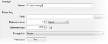
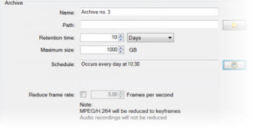
Example: These storages (image to the left) have a retention time of 4 days and the following archive (image to the right) a retention time of 10 days. Archiving is set to occur every day at 10:30, ensuring a much more frequent archiving than retention time.
|
|
|
|---|
You can also control archiving by use of rules and events.
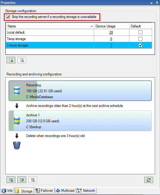
Specify behavior when recording storage is unavailable
By default, the recording server keeps running if a recording storage becomes unavailable. If your system is configured with failover recording servers, you can specify the recording server to stop running, to make the failover servers take over:
- On the relevant recording server, go to the Storage tab.
- Select the Stop the recording server if a recording storage is unavailable option.
Add a new storage
When you add a new storage, you always create one recording storage with a predefined recording database named Recording. You cannot rename the database. Apart from the recording storage, a storage can contain a number of archives.
- To add an extra storage to a selected recording server, click the
 button located below the Storage configuration list. This opens the Storage and Recording Settings dialog box.
 - Specify the relevant settings (see Storage and Recording Settings properties).
- Click OK.
If needed, you are now ready to create archive(s) within your new storage.
Create an archive within a storage
A storage has no default archive, but you can create archives as needed.
- Select the relevant storage in the Recording and archiving configuration list.
- Click the
 button below the Recording and archiving configuration list.
 - In the Archive Settings dialog box, specify the required settings (see Archive Settings properties).
- Click OK.
Attach a device or group of devices to a storage
Once a storage is configured for a recording server, you can enable it for individual devices such as cameras, microphones or speakers or a group of devices. You can also select which of a recording server's storage areas you want to use for the individual device or the group.
- Expand Devices and select either Cameras, Microphones or Speakers as required.
- Select the device or a device group.
- Select the Record tab.
- In the Storage area, select Select.
- In the dialog box that appears, select the database that should store the recordings of the device and then click OK.
- In the toolbar, click Save.
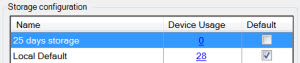
When you click the device usage number for the storage area on the Storage tab of the recording server, the device is visible in the message report that appears.
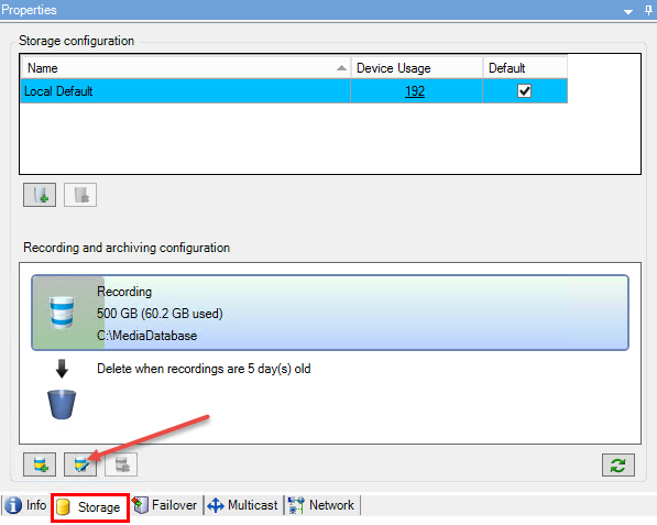
Edit settings for a selected storage or archive
- To edit a storage, select its recording database in the Recording and archiving configuration list. To edit an archive, select the archive database.
- Click the Edit Recording Storage button
 located below the Recording and archiving configuration list.
 - Either edit a recording database or edit an archive.
If you change the maximum size of a database, the system auto-archives recordings that exceed the new limit. It auto-archives the recordings to the next archive or deletes them depending on archiving settings.
Enable digital signing for export
Available functionality depends on the system you are using. See https://www.milestonesys.com/solutions/platform/product-index/ for more information.
You can enable digital signing for recorded video, so that client users can verify that the recorded video has not been tampered with since it was recorded. Verifying the authenticity of the video is something that the user does in XProtect Smart Client – Player after the video has been exported.
Signing must also be activated in XProtect Smart Client in the Export dialog. Otherwise, the Verify Signatures button in XProtect Smart Client – Player is not displayed.
- In the Site Navigation pane, expand the Servers node.
- Click Recording Servers.
- In the overview pane, click the recording server you want to enable signing for.
- At the bottom of the Properties pane, click the Storage tab.
- In the Recording and archiving configuration section, double-click the horizontal bar that represents the recording database. The Storage and Recording Settings window appears.
- Select the Signing check box.
- Click OK.
Encrypt your recordings
Available functionality depends on the system you are using. See https://www.milestonesys.com/solutions/platform/product-index/ for more information.
You can secure your recordings by enabling encryption on your recording servers' storage and archives. You can choose between light and strong encryption. When you enable encryption, you must also specify a related password.
Enabling or changing encryption settings or password can potentially be time consuming, depending on the size of the database and performance of the drive. You can follow the progress under Current Tasks.
Do not stop the recording server while this task is ongoing.
- Click the Edit Recording Storage button below the Recording and archiving configuration list.
- In the dialog box that appears, specify encryption level.
- You are automatically directed to Set Password dialog box. Enter password and click OK.
Back up archived recordings
Many organizations want to back up their recordings by using tape drives or similar. Exactly how you do this is highly individual and depends on the backup media used in your organization. However, the following is worth bearing in mind:
Back up archives rather than camera databasesAlways create backups based on the content of archives, not based on individual camera databases. If you create backups based on the content of individual camera databases, you may cause sharing violations or other malfunctions.
When scheduling a backup, make sure the backup job does not overlap with your specified archiving times. To view each recording server's archiving schedule in each of a recording server's storage areas, see the Storage tab.
Know your archive structure so that you can target backupsWhen you archive recordings, you store them in a certain sub-directory structure within the archive.
During all regular use of your system, the sub-directory structure is completely transparent to the system's users when they browse recordings with XProtect Smart Client. This is true both with archived and non-archived recordings. It is relevant to know the sub-directory structure (see Archive structure (explained) if you want to back up your archived recordings (see Backing up and restoring system configuration).
Archive structure (explained)
When you archive recordings, they are stored in a certain sub-directory structure within the archive.
During all regular use of your system, the sub-directory structure is completely transparent to the system's users, as they browse all recordings with the XProtect Smart Client regardless of whether the recordings are archived or not. Knowing the sub-directory structure is primarily interesting if you want to back up your archived recordings.
In each of the recording server's archive directories, the system automatically creates separate sub-directories. These sub-directories are named after the name of the device and the archive database.
Because you can store recordings from different cameras in the same archive, and since archiving for each camera is likely to be performed at regular intervals, further sub-directories are also automatically added.
These sub-directories each represent approximately an hour's worth of recordings. The one-hour split makes it possible to remove only relatively small parts of an archive's data if you reach the maximum allowed size of the archive.
The sub-directories are named after the device, followed by an indication of where the recordings came from (edge storage or via SMTP), plus the date and time of the most recent database record contained in the sub-directory.
Naming structure...[Storage Path]\[Storage name]\[device-name] - plus date and time of most recent recording]\
If from edge storage:
...[Storage Path]\[Storage name]\[device-name] (Edge) - plus date and time of most recent recording]\
If from SMTP:
...[Storage Path]\[Storage name]\[device-name] (SMTP) - plus date and time of most recent recording]\
Real life example...F:\OurArchive\Archive1\Camera 1 on Axis Q7404 Video Encoder(10.100.50.137) - 2011-10-05T11:23:47+02:00\
Sub-directoriesEven further sub-directories are automatically added. The amount and nature of these sub-directories depend on the nature of the actual recordings. For example, several different sub-directories are added if the recordings are technically divided into sequences. This is often the case if you have used motion detection to trigger recordings.
- Media: This folder contains the actual media that is either video or audio (not both)
- MotionLevel: This folder contains motion level grids generated from the video data using our motion detection algorithm. This data allows the Smart Search feature in XProtect Smart Client to do very fast searches
- Motion: In this folder, the system stores motion sequences. A motion sequence is a time slice for which motion has been detected in the video data. This information is, for example, used in the time line in XProtect Smart Client
- Recording: In this folder, the system stores recording sequences. A recording sequence is a time slice for which there are coherent recordings of media data. This information is, for example, used to draw the time line in XProtect Smart Client
- Signature: This folder holds the signatures generated for the media data (in the Media folder). With this information, you can verify that the media data has not been tampered with since it was recorded
If you want to back up your archives, you can target your backups if you know the basics of the sub-directory structure.
Examples of backupTo back up the content of an entire archive, back up the required archive directory and all of its content. For example, everything under:
...F:\OurArchive\
To back up the recordings from a particular camera from a particular period of time, back up the contents of the relevant sub-directories only. For example, everything under:
...F:\OurArchive\Archive1\Camera 1 on Axis Q7404 Video Encoder(10.100.50.137) - 2011-10-05T11:23:47+02:00\
Delete an archive from a storage
- Select the archive from the Recording and archiving configuration list.
- Click the
 button located below the Recording and archiving configuration list.
 - Click Yes.
- If the archive is unavailable, for example, offline, you need to restore the connection before you can delete the archive.
It is only possible to delete the last archive in the list. The archive does not have to be empty.
Delete a storage
You cannot delete the default storage or storages that devices use as the recording storage for live recordings.
This means that you may need to move devices (see Move hardware) and any not yet archived recordings to another storage before you delete the storage.
- To see the list of devices that use this storage, click the device usage number.
If the storage has data from devices that have been moved to another recording server, a warning appears. Click the link to see the list of devices.
- Follow the steps in Move non-archived recordings from one storage to another.
- Continue until you have moved all devices.
- Select the storage that you want to delete.
- Click the
 button located below the Storage configuration list.
 - Click Yes.
Move non-archived recordings from one storage to another
You move recordings from one live recording database to another from the Record tab of the device.
- Select the device type. In the Overview pane, select the device.
- Click the Record tab. In the upper part of the Storage area, click Select.
- In the Select Storage dialog box, select the database.
- Click OK.
- In the Recordings Action dialog box, select if you want to remove already existing - but non-archived - recordings to the new storage or if you want to delete them.
- Click OK.
Storage and Recording Settings properties
Available functionality depends on the system you are using. See https://www.milestonesys.com/solutions/platform/product-index/ for more information.
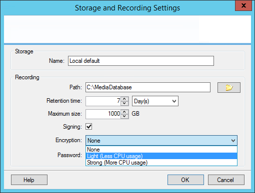
In the Storage and Recording Settings dialog box, specify the following:
|
Name |
Description |
|---|---|
| Name |
Rename the storage if needed. Names must be unique. |
| Path |
Specify the path to the directory to which you save recordings in this storage. The storage does not necessarily have to be located on the recording server computer. If the directory does not exist, you can create it. Network drives must be specified by using UNC (Universal Naming Convention) format, example: \\server\volume\directory\. |
| Retention time |
Specify for how long recordings should stay in the archive before they are deleted or moved to the next archive (depending on archive settings). |
| Maximum size |
Select the maximum number of gigabytes of recording data to save in the recording database. Recording data in excess of the specified number of gigabytes is auto-moved to the first archive in the list - if any is specified - or deleted. When less than 5GB of space is free, the system always auto-archives (or deletes if no next archive is defined) the oldest data in a database. If less than 1GB space is free, data is deleted. A database always requires 250MB of free space. If you reach this limit (if data is not deleted fast enough), no more data is written to the database until you have freed enough space. The actual maximum size of your database is the amount of gigabytes you specify, minus 5GB. |
| Signing |
Enables a digital signature to the recordings. This means, for example, that the system confirms that exported video has not been modified or tampered with when played back. The system uses the SHA-2 algorithm for digital signing. |
| Encryption |
Select the encryption level of the recordings:
The system uses the AES-256 algorithm for encryption. If you select Light, a part of the recording is encrypted. If you select Strong, the whole recording is encrypted. If you choose to enable encryption, you must also specify a password below. |
| Password |
Enter a password for the users allowed to view encrypted data. Milestone recommends that you use strong passwords. Strong passwords do not contain words that can be found in a dictionary or are part of the user's name. They include eight or more alpha-numeric characters, upper and lower cases, and special characters. |
Archive Settings properties
In the Archive Settings dialog box, specify the following:
|
Name |
Description |
|---|---|
| Name |
Rename the storage if needed. Names must be unique. |
| Path |
Specify the path to the directory to which you save recordings in this storage. The storage does not necessarily have to be located on the recording server computer. If the directory does not exist, you can create it. Network drives must be specified by using UNC (Universal Naming Convention) format, example: \\server\volume\directory\. |
| Retention time |
Specify for how long recordings should stay in the archive before they are deleted or moved to the next archive (depending on archive settings). |
| Maximum size |
Select the maximum number of gigabytes of recording data to save in the recording database. Recording data in excess of the specified number of gigabytes is auto-moved to the first archive in the list - if any is specified - or deleted. When less than 5GB of space is free, the system always auto-archives (or deletes if no next archive is defined) the oldest data in a database. If less than 1GB space is free, data is deleted. A database always requires 250MB of free space. If you reach this limit (if data is not deleted fast enough), no more data is written to the database until you have freed enough space. The actual maximum size of your database is the amount of gigabytes you specify, minus 5GB. |
| Schedule |
Specify an archiving schedule that outlines the intervals with which the archiving process should start. You can archive very frequently (in principle every hour all year round), or very infrequently (for example, every first Monday of every 36 months). |
| Reduce frame rate |
To reduce FPS when archiving, select the Reduce frame rate check box and set a frame per second (FPS). Reduction of frame rates by a selected number of FPS makes your recordings take up less space in the archive, but it also reduces the quality of your archive. 0.1 = 1 frame per 10 seconds. |
Failover tab (recording server)
Available functionality depends on the system you are using. See https://www.milestonesys.com/solutions/platform/product-index/ for more information.
If your organization uses failover recording servers, use the Failover tab to assign failover servers to recording servers, see Failover tab properties.
For details on failover recording servers, installation and settings, failover groups and their settings, see Failover recording servers (explained).
Assign failover recording servers
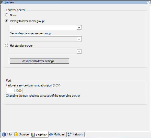
On the Failover tab of a recording server, you can choose between three types of failover setups:
- No failover setup
- A primary/secondary failover setup (cold standby)
- A hot standby setup
If you select b and c, you must select the specific server/groups. With b, you can also select a secondary failover group. If the recording server becomes unavailable, a failover recording server from the primary failover group takes over. If you have also selected a secondary failover group, a failover recording server from the secondary group takes over in case all failover recording servers in the primary failover group are busy. In this way, you only risk not having a failover solution in the rare case when all failover recording servers in the primary, as well as in the secondary, failover group are busy.
- In the Site Navigation pane, select Servers > Recording Servers. This opens a list of recording servers.
- In the Overview pane, select the wanted recording server, go to the Failover tab.
- To choose failover setup type, select between:
- None
- Primary failover server group/Secondary failover sever group
- Hot standby server
You cannot select the same failover group as both primary and secondary failover group nor select regular failover servers already part of a failover group as hot standby servers.
- Next, click Advanced failover settings. This opens the Advanced Failover Settings window, listing all devices attached to the selected recording server. If you selected None, the advanced failover settings are also available. The system keeps any selections for later failover setups.
- To specify the level of failover support, select Full Support, Live Only or Disabled for each device in the list. Click OK.
- In the Failover service communication port (TCP) field, edit the port number if needed.
If you enable failover support and the recording server is configured to keep running if a recording storage is unavailable, the failover recording server will not take over. To make the failover support work, you must select the Stop the recording server if a recording storage is unavailable option on the Storage tab.
Failover tab properties
|
Name |
Description |
|---|---|
| None |
Select a setup without failover recording servers. |
| Primary failover server group / Secondary failover server group |
Select a regular failover setup with one primary and possibly one secondary failover server group. |
| Hot standby server |
Select a hot standby setup with one dedicated recording server as hot standby server. |
| Advanced failover settings |
Opens the Advanced Failover Settings window:
|
| Failover service communication port (TCP) |
By default, the port number is 11000. You use this port for communication between recording servers and failover recording servers. If you change the port, the recording server must be running and must be connected to the management server. |
Multicast tab (recording server)
Your system supports multicasting of live streams from recording servers. If multiple XProtect Smart Client users want to view live video from the same camera, multicasting helps saving considerable system resources. Multicasting is particularly useful if you use the Matrix functionality, where multiple clients require live video from the same camera.
Multicasting is only possible for live streams, not for recorded video/audio.
If a recording server has more than one network interface card, it is only possible to use multicast on one of them. Through the Management Client you can specify which one to use.
If you are using failover servers, remember to also specify the IP address of the network interface card on the failover servers (see Multicast tab (failover server)).
The successful implementation of multicasting also requires that you have set up your network equipment to relay multicast data packets to the required group of recipients only. If not, multicasting may not be different from broadcasting, which can significantly slow down network communication.
Multicasting (explained)
In regular network communication, each data packet is sent from a single sender to a single recipient - a process known as unicasting. But with multicasting you can send a single data packet (from a server) to multiple recipients (clients) within a group. Multicasting can help save bandwidth.
- When you use unicasting, the source must transmit one data stream for each recipient
- When you use multicasting, only a single data stream is required on each network segment
Multicasting as described here is not streaming of video from camera to servers, but from servers to clients.
With multicasting, you work with a defined group of recipients, based on options such as IP address ranges, the ability to enable/disable multicast for individual cameras, the ability to define largest acceptable data packet size (MTU), the maximum number of routers a data packet must be forwarded between (TTL), and so on.
Multicast streams are not encrypted, even if the recording server uses encryption.
Multicasting should not be confused with broadcasting, which sends data to everyone connected to the network, even if the data is perhaps not relevant for everyone:
|
Name |
Description |
|---|---|
| Unicasting |
Sends data from a single source to a single recipient. |
| Multicasting |
Sends data from a single source to multiple recipients within a clearly defined group. |
| Broadcasting |
Sends data from a single source to everyone on a network. Broadcasting can therefore significantly slow down network communication. |
Enable multicasting for the recording server
To use multicasting, your network infrastructure must support the IP multicasting standard IGMP (Internet Group Management Protocol).
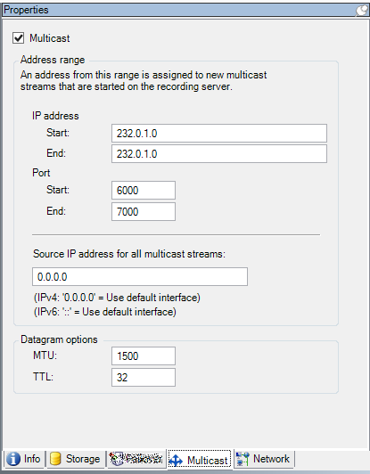
- On the Multicast tab, select the Multicast check box
If the entire IP address range for multicast is already in use on one or more recording servers, you first release some multicast IP addresses before you can enable multicasting on additional recording servers.
Multicast streams are not encrypted, even if the recording server uses encryption.
Assign IP address range
Specify the range you want to assign as addresses for multicast streams from the selected recording server. The clients connect to these addresses when the users view multicast video from the recording server.
For each multicast camera feed, the IP address and port combination must be unique (IPv4 example: 232.0.1.0:6000). You can either use one IP address and many ports, or many IP addresses and fewer ports. By default, the system suggests a single IP address and a range of 1000 ports, but you can change this as required.
IP addresses for multicasting must be within the range defined for dynamic host allocation by IANA. IANA is the authority overseeing global IP address allocation.
|
Name |
Description |
|---|---|
| IP address |
In the Start field, specify the first IP address in the required range. Then specify the last IP address in the range in the End field. |
| Port |
In the Start field, specify the first port number in the required range. Then specify the last port number in the range in the End field. |
| Source IP address for all multicast streams |
You can only multicast on one network interface card, so this field is relevant if your recording server has more than one network interface card or if it has a network interface card with more than one IP address. To use the recording server's default interface, leave the value 0.0.0.0 (IPv4) or :: (IPv6) in the field. If you want to use another network interface card, or a different IP address on the same network interface card, specify the IP address of the required interface.
|
Specify datagram options
Specify the settings for data packets (datagrams) transmitted through multicasting.
|
Name |
Description |
|---|---|
| MTU |
Maximum Transmission Unit, the largest allowed physical data packet size (measured in bytes). Messages larger than the specified MTU are split into smaller packets before they are sent. The default value is 1500, which is also the default on most Windows computers and Ethernet networks. |
| TTL |
Time To Live, the largest allowed number of hops a data packet should be able to travel before it is discarded or returned. A hop is a point between two network devices, typically a router. Default value is 128. |
Enable multicasting for individual cameras
Multicasting only works when you enable it for the relevant cameras:
- Select the recording server and select the required camera in the Overview pane.
- On the Client tab, select the Live multicast check box. Repeat for all relevant cameras.
Multicast streams are not encrypted, even if the recording server uses encryption.
Network tab (recording server)
You define a recording server's public IP address on the Network tab.
Why use a public address?
When an access client, such as XProtect Smart Client, connects to a surveillance system, an amount of initial data communication, including the exchange of contact addresses, is shared in the background. This happens automatically, and is completely transparent to the users.
Clients may connect from the local network as well as from the Internet, and in both cases the surveillance system must provide suitable addresses so the clients can get access to live and recorded video from the recording servers:
- When clients connect locally, the surveillance system should reply with local addresses and port numbers
- When clients connect from the internet, the surveillance system should reply with the recording server's public address. This is the address of the firewall or NAT (Network Address Translation) router, and often also a different port number. The address and the port can then be forwarded to the server's local address and port.
To provide access to the surveillance system from outside a NAT (Network Address Translation) firewall, you can use public addresses and port forwarding. This allows clients from outside the firewall to connect to recording servers without using VPN (Virtual Private Network). Each recording server can be mapped to a specific port and the port can be forwarded through the firewall to the server's internal address
Define public address and port
- To enable public access, select the Enable public access check box.
- Define the recording server's public address. Enter the address of the firewall or NAT router so clients that access the surveillance system from the Internet can connect to the recording servers.
- Specify a public port number. It is always a good idea that port numbers used on the firewall or NAT router are different from the ones used locally.
If you use public access, configure the firewall or NAT router so requests sent to the public address and port are forwarded to the local address and port of relevant recording servers.